
Objective
For this application test of soldering copper pins onto a PCB, the customer needs to define a new process for manufacturing a small PCB assembly, due to a material change for one of the components.
The customer needs to attach copper pins to a PCB (this is a small potentiometer assembly). For the current process, the customer ultrasonically welds the copper pins onto the substrate of the PCB. However, they are changing to a stiff copper pin which cannot be ultrasonically welded. This application test is to show that induction is a viable process for soldering the copper pins to the PCB, while meeting the target production rate of an average of 3 pins to one PCB every second.
Equipment
SBT-3/1000 Power Supply, operating up to 1 MHz
HSB-3 Heat Station
Materials
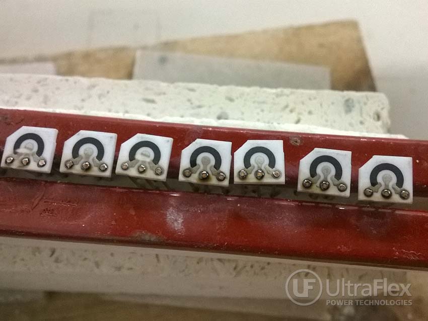
• Printed circuit board (PCB)– substrate 0.217″ (5.512mm) x 0.0197″ (.5mm) x 0.025″ (.635mm) thick plated copper
• Copper pins, 0.016″ (.406mm) diameter, 0.475″ (12.065mm) long, 3 pins per PCB (mechanically connected prior to soldering).
Key Parameters
Power: 2.4 kW
Time: 12 sub assembly boards in 3.5 seconds
Temperature: Tested temperature 500°F (260°C) +
Process:
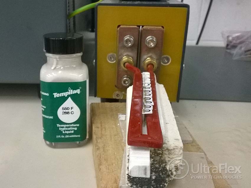
- For this application test of soldering copper pins onto a PCB, we need to use induction to heat the pins to approximately 500°F (260°C). During the assembly process, the heated pins will conduct heat into the solder paste, and cause the solder paste to flow. For this test, the solder paste is not important – our goal is to confirm that the copper pins will met the target temperature of approximately 500°F (260°C). Tempilaq, a temperature monitoring paint, is painted onto the pins, so we can monitor their temperature.
- Some preliminary testing was conducted to determine the best position of the PCBs within the induction coil. Testing was done for both parts under the coil and above the coil. Parts that were positioned under the coil did not reach temperature, while parts positioned above the coil were able to heat to 500°F (260°C).
- The testing setup simulates use of an automated conveyor, where subassemblies can be moved through the center of the hairpin coil exposing the pins to the RF field. The substrate was set at 0.092” (2.337mm) above the coil turn. This process resulted in the ability to heat 12 sub assemblies to a temperature above 500°F (260°C) in a total cycle time of 3.5 seconds (about 0.3 seconds / PCB). This cycle time will permit either a much faster process potential.
- The final coil design will utilize the hairpin coil used in this application test, but will modify the coil to include a “bridge” entry and exit, which provide clearance for the small PCB to move through the coil.
Results/Benefits:
For this application test of Induction soldering copper pins onto a PCB, the test results indicate that the process of heating the pad/pin interface on the substrate can be done at the rate of 1 PCB assembly every 0.3 seconds, which exceeds the target of 1 second per PCB. By using UPT-SBT3/1000 system, the customer’s production rates can grow to meet increasing demand for the parts.
Pictures
Subscribe to our YouTube Channel
Video
Request information or contact us about this application.
