
Objective
Demonstrating braze and braze time using the U-Braze 10 kW system and available split lab coil
Test 1
Equipment
U Braze 10/150
Materials
• Copper tubing – Suction Tube
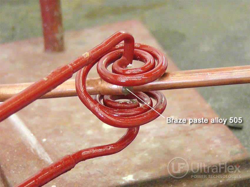
• Braze paste
Key Parameters
Power: 9.58 kW
Temperature: Approximately 1500° F (815° C)
Time: 5 – 5.2 sec
Test 2
Equipment
U Braze 10/150
Materials
• Copper tubing – Condenser tube
• Braze paste
Key Parameters
Power: 8.83 kW
Temperature: Approximately 1300° F (704° C)
Time: 2 sec
Process:
Test 1
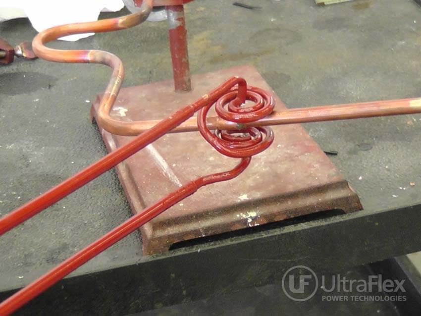
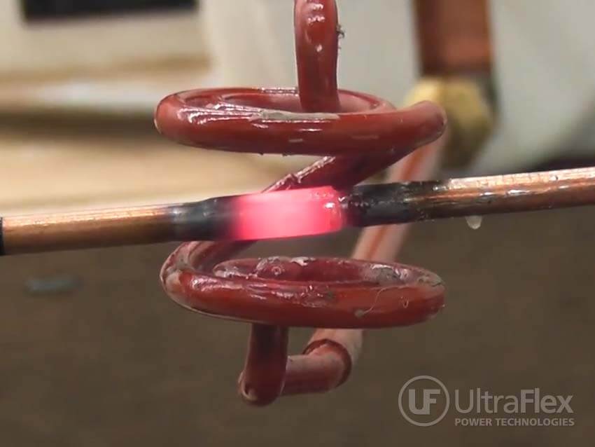
As only one assembly was provided for the test, we set up a test load using a heavy wall 5/16” copper tubing set up such as one tube accepted the other at a formed open flange end. Heat time was estimated based on using tempilaque paint to indicate the temperature. The test assembly, (followed by the provided components) were assemble with a coating of 505 alloy braze paste and placed in the lab test coil per the attached photographs) A heat cycle 5 – 5.2 seconds was found to flow the alloy and make the joint.
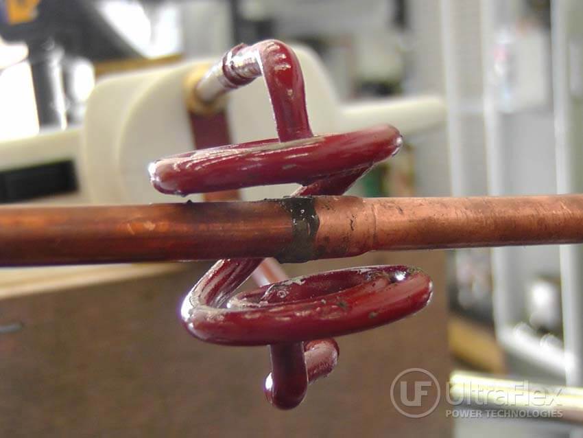
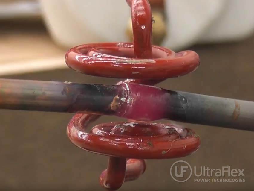
Test 2:
The smaller tube assembly (condenser tube) was assembled and a ring from the supplied braze alloy (silver solder) was formed and place at the intersection of the two tube (see attached photographs). A heat time of 2 seconds was sufficient to flow the alloy and complete the joint.
Results/Benefits:
- As demonstrated, the Ultraflex U braze system is capable of heating both the largest and smallest tube to tube sections to complete a brazed joint. Heat times using an available test coil are within the production heat time expectations required by Electrolux.
- Ultraflex will require a full assembly for review in order to develop the final coil design that can accommodate all 12 joints indicated on your layout photograph. It is necessary to know and see the clearances between the tube connections to be brazed and the steel compressor section to insure that the steel housing is not affected by the resulting RF field created at the load coil. This final design may require the addition of ferrite materials in the coil that will serve to focus the RF field to the copper leads and not to the steel housing.
- Initial tests were completed on the U Braze 10 kW utilizing an available lab coil. The production coil will be contained in a none-conductive housing that will permit the operator to use it to locate the coil against the copper leads for accurate and positive heating location for the braze process. The production coil design will incorporate shorter leads than the test coil and be configured such that the heat cycles will be improved (shorter heat times).
- Ultraflex can provide the system with an optional process control. This will effectively be a programmed process cycle that will be developed for each joint listed on the assembly photograph supplied with the application request from Electrolux. Each of the 12 joints will be programmed sequentially to accommodate each particular joint – this will permit the operator to move in the same sequence as programmed from joint 1 to joint 12. Each cycle of the U braze coil/handle will move the process from joint 1 (heat time and % of power) to joint 2 (heat time and % power) etc. though to joint 12. The sequence, once entered, would need to be followed for each assembly. This will take the guess work out of braze time per joint to provide repeatability in the process.
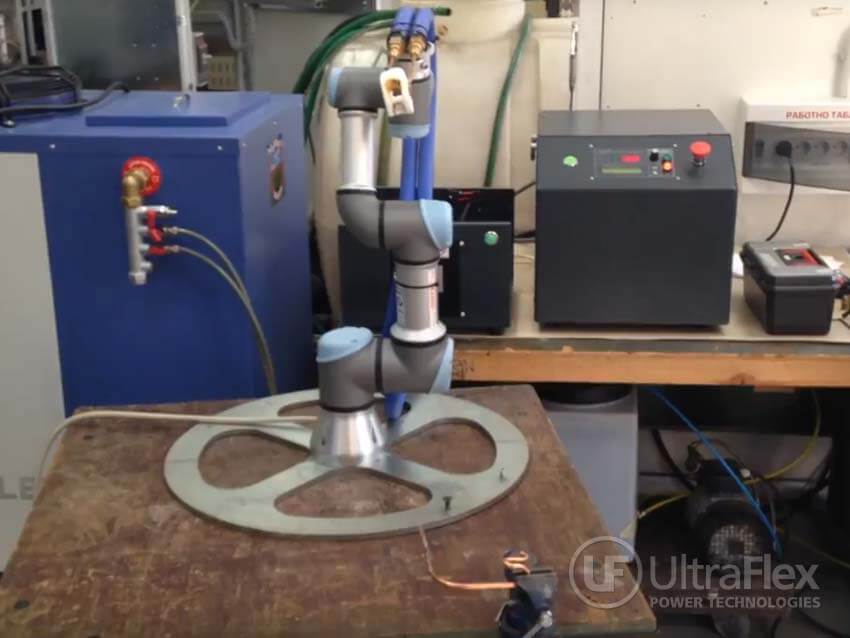
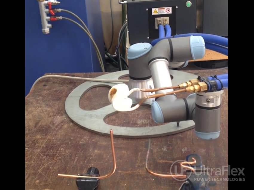
- Another option for consideration would be to consider the Ultraflex Robotic Arm option. This option supports the coil/ coil housing and actuates the assembly when programmed to place the coil at each joint area. The support arm rotates and moves the coil/coil housing to the proper position and angle for each joint assuring the soil position and heat time. (See attached video link) Note: the link also depicts the coil in the non-conductive housing as noted in item 3 above.)
Pictures

Video
Request information or contact us about this application.